Our Development History
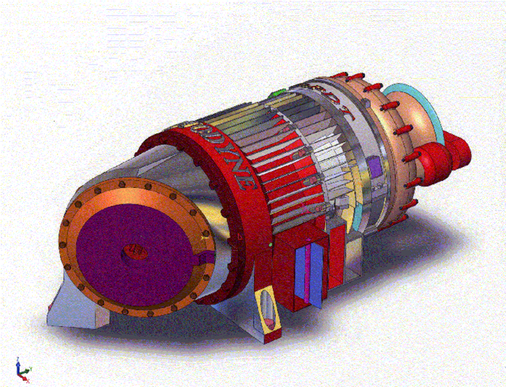
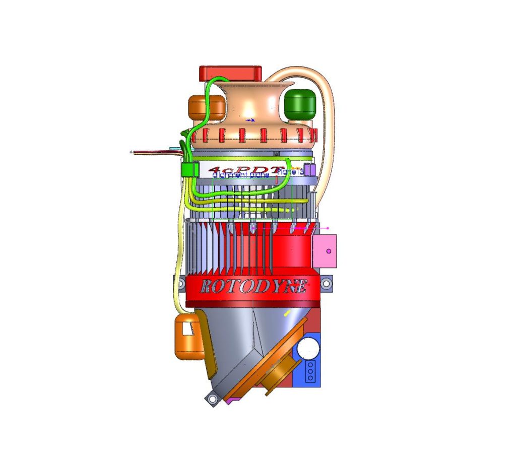
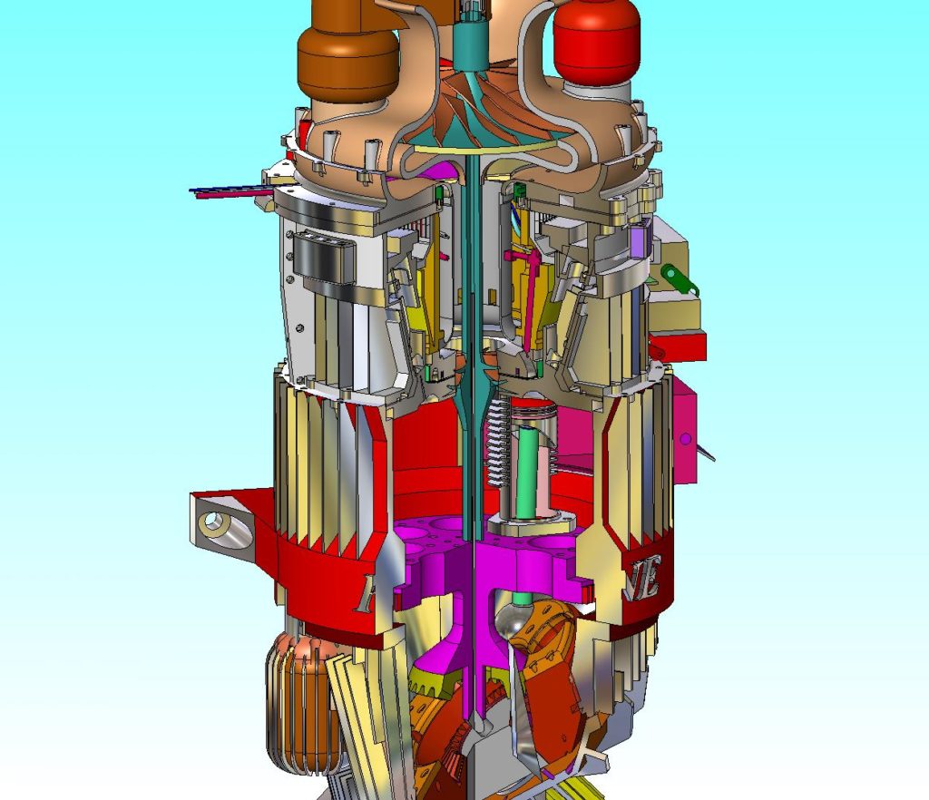
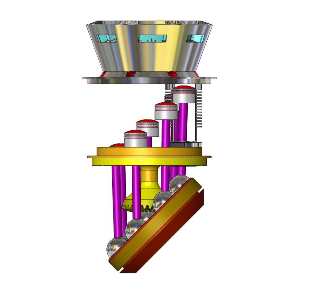
The first Rotodyne Engine concept happened for Doug about 20 years ago and it was a standard barrel-engine design with upright cylinders. There were many objectives that we accomplished over the years including a full solid works model of all the parts all interconnected and working, as well as a computational spreadsheet that allows us to enter design variables to optimize the piston motion for a constant volume combustion cycle. This work product we developed was verified by the Southwest Research Institute (SwRI) and their results and the supporting documents are presented below, along with their suggestion for the next steps in the development.
Case Studies
Computational Fluid Dynamics (CFD) modeling of the combustion process with 3 different piston dwell scenarios.
SwRI Assessment Report
The Southwest Research Institute’s evaluation of the Rotodyne Engine lays out the merits of the engine as well as the engineering challenges.
The Rotodyne Engine Achieves 40+% Improved Brake Thermal Efficiency as follows:
| CASE RUN 11 | Traditional IC BTE | Traditional IC ITE | Rotodyne BTE | Rotodyne ITE | BTE % improvement |
| Base Engine – case run 11 | 27% | 29% | 31% | 36% | 15% |
| w/ 95% volumetric efficiency | 27% | 29% | 35% | 40% | 30% |
| w/ improved FMEP loss | 27% | 29% | 37% | 40% | 37% |
| w/ thermal coasted piston/head/valves | 29% | 31% | 41% |
44% (46% theoretical max) |
41% |
| w/ quasi Atkins cycle | 35% | 37% | 47% | 50% | 34% |
| Base engine w/ diesel, direct injection | 43% | 55% | 50% | ||
BTE Assumptions & Questions
- Volumetric Efficiency (VE) Issues
- (a) Current VE is approx. 85% – how high can we get it? 95% would increase BTE by 4%
- Compression ratio issues
- (a) current compression ratio is 10:1
- (b) pros/cons of a quasi Atkins cycle where we set a static compression ratio @ 20:1 but close the valve late so that there is a dynamic compression ratio of 10:1, resulting in an increased expansion (DelataV)
- (c) effect of running E85 fuel on compression ratio and resulting BTE (does Rotodyne see a greater advantage than an IC)
- (d) effect of running diesel cycle w/ direct injection on the compression ratio and resulting BTE (does Rotodyne see a greater advantage than an IC)
- Advantages/Disadvantages of speed
- (a) VE Increase
- (b) Friction Increase
- (c) Inertia Increase
- (d) Power density increase
- (e) determination of additional engine speeds for further case study – run 2 additional speeds (1 higher and 1 lower) so that we can extrapolate a curve
- Advantages/Disadvantages of Coatings
- (a) Thermal Gradient Coatings (zirconia)– Rotodyne should see a bigger advantage (+4% BTE) compared to an IC (+2% BTE) due to ~100bar peak pressure
- Potential improvements in FMEP
- (a) current FMEP is 1.6 bar—can it be reduced to 1bar (same as in an IC) due to
- (b) back pressure on exhaust seal, carbon-to-carbon seal
- (c) effect of the longer Rotodyne torque arm on FMEP to reduce FMEP
- Potential BMEP/IMEP from the Rotodyne concept
- Potential advantages of the longer Rotodyne torque arm – what does it mean?
- (a) How much torque does an IC produce at 3600 rpm compared to Rotodyne (are we higher torque a lower speed because of the longer torque arm?)
- Potential final case studies to confirm assumptions
- (a) in the kinematic model confirm whether torque is developed during the dwell period of case 11 – apply peak pressure at 0 degrees? What would that mean?
Next Steps
SwRI set forth its recommendations for the next steps in the development of the Rotodyne Engine which are engineering related and directed to optimizing the piston motion for greatest efficiency advantage and then engineering the mechanical tolerances before building the prototype. The full report is available below:
Click here to download the SwRI Rotodyne Thermo Analysis Proposal
A Distributed Engine Development Strategy
Rotodyne Engine Development, LLC has been created for the purposes of soliciting a grassroots engine development strategy in pursuit of production engines employing the constant volume combustion cycle.
Rotodyne Engine Development, LLC seeks to enlist motivated engineers, engine builders, fabricators, and others to partner in the building and testing of the first prototype Rotodyne Engine. More specifically, Rotodyne Engine Development, LLC seeks to make available all of its research and development available to select parties who are interested in furthering the vision of The Rotodyne Engine and sharing in the financial rewards associated with the sale and/or licensing of piston dwell/constant volume combustion technology under US Patent 7,677,210.
A working prototype the Rotodyne Engine is set to disrupt the $500B standby generator market. It is the first and most practical multi-cylinder engine exhibiting the textbook constant volume combustion cycle. Other markets and applications including the hybrid vehicle market worldwide provide further incentives.
Rotodyne Engine Development, LLC is making the following information available to parties interested in being part of this grassroots Rotodyne Engine Development Project:
Computational Piston Motion Spreadsheet
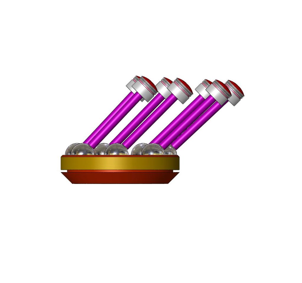
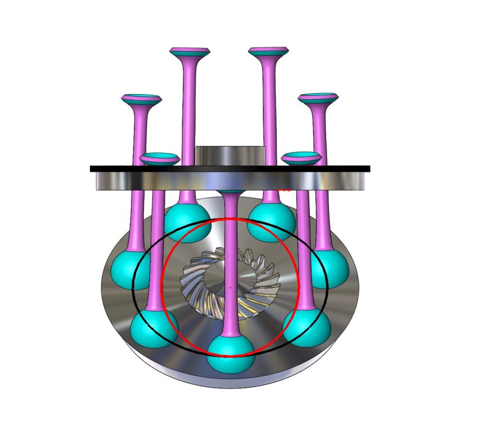
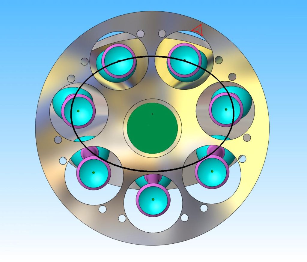
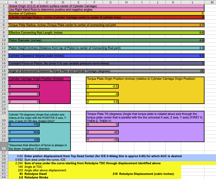
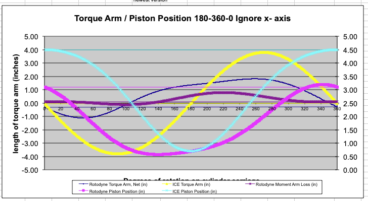
This proprietary computational spreadsheet visualizes adjustments to the design parameters in a dynamic graph of the piston motion vs. crank angle. There are 16 variables that are modelled in this spreadsheet including the angle of advancement or retardation between the Torque Plate and the Cylinder Carriage, the offset of the Torque Plate center with respect to the center of the Cylinder Carriage, the tilt of the Torque Plate with respect to the Cylinder Carriage, and the pitch and yaw of the Cylinder axis.
The Solidworks Model
Rotodyne Engine Development will make available the entire Solidworks virtual model of the Rotodyne Engine to its partners to facilitate the production of the prototype(s) which includes the following parts, and linkage assemblies, etc:
| Part No. | Part Name | Quantity | Total Cost | Image (.jpg) | File Name | Volume (cubic cm) |
| 1 | cam carriage with 3 cams | 1 | ||||
| 2 | cam support with intake duct | 1 | ||||
| 3 | middle cam support | 1 | ||||
| 4 | lower cam support | 1 | ||||
| 5 | cylinder carriage | 1 | ||||
| 6 | cylinder head | 1 | ||||
| 7 | intake manifold | 1 | ||||
| 8 | combustion intake tube | 1 | ||||
| 9 | Central support A | 1 | ||||
| 10 | central support B | 1 | ||||
| 11 | cardan gear with clear holes | 1 | ||||
| 12 | cardan gear with tapped holes | 1 | ||||
| 13 | power transfer gear assembly | 1 | ||||
| 14 | power transfer gear | 1 | ||||
| 15 | crank gear | 1 | ||||
| 16 | oil pump impellor | 1 | ||||
| 17 | slave oil pump impellor | 1 | ||||
| 18 | 100 tooth ring gear | 1 | ||||
| 19 | oil pump drive gear | 1 | ||||
| 20 | oil pump slave gear | 1 | ||||
| 21 | slave oil pump shaft | 1 | ||||
| 22 | piston | 5 | ||||
| 23 | rod | 5 | ||||
| 24 | rod capture at piston | 5 | ||||
| 25 | rod capture at torque plate | 5 | ||||
| 26 | torque plate | 1 | ||||
| 27 | intake rocker | 5 | ||||
| 28 | intake lifter | 5 | ||||
| 29 | intake rocker cover | 5 | ||||
| 30 | intake valve | 5 | ||||
| 31 | exhaust rocker | 5 | ||||
| 32 | exhaust lifter | 5 | ||||
| 33 | exhaust rocker cover | 5 | ||||
| 34 | exhaust valve | 5 | ||||
| 35 | spark plug | 5 | ||||
| 36 | spring retainer | 10 | ||||
| 37 | spring retainer clip | 8 |
Rotodyne Engine Development, LLC is now executing a distributed engine development strategy to partner with independent engine builder(s) to build and test a prototype of the revolutionary Rotodyne Engine, in order to then sell and/or license the technology under US Patent 7,677,210, which is the pioneering patent for constant volume combustion. All engine builder participants will receive a share of the profits and proceeds from all sales and licensing.
The Rotodyne Engine is set to disrupt the $500B standby generator market. It is the first and most practical multi-cylinder engine to employ the textbook constant volume combustion cycle. Other markets and applications worldwide provide further incentive.
Interested parties should contact us.